
An oil-in-water alarm should start a controlled investigation. It may represent a genuine process event, a change in the sample reaching the sensor, or a measurement condition that needs attention. Recalibrating immediately can obscure the evidence you need to tell those possibilities apart.
For UK industrial water and effluent teams, the first step is to follow the site’s alarm response procedure and preserve the trend. Record the time, process conditions and any operator observations before adjusting the instrument.
Match the sample to the event
A laboratory bottle collected later or from a different point may not represent the water that triggered the online alarm. Record where and when each sample was taken, how it was handled and the elapsed time before analysis. If the process changes quickly, timing differences can be significant.
For a side-stream installation, check that water is reaching the measurement point as intended. Review flow, isolation valves, sample-line condition and any recent maintenance. For an immersed sensor, confirm that the measurement area remains representative of the stream.
Check what the instrument is calibrated to detect
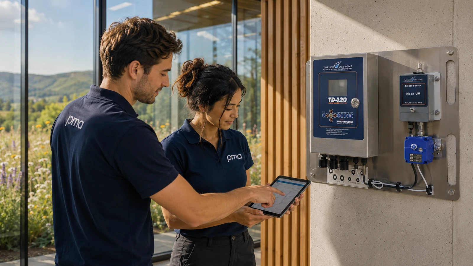
The Turner Designs Hydrocarbon Instruments TD-120 uses fluorescence for continuous oil-in-water monitoring. The response depends on the hydrocarbon and the selected optical configuration. A calibration suited to one oil should not simply be assumed to represent a different product.
PMA’s oil-in-water analyser microsite covers continuous and portable measurement options. Discuss the actual oil or fuel, expected concentration and sample matrix when selecting an instrument or reviewing an existing calibration.
Understand the calibration basis
A calibration is only useful when the oil, sample and measurement basis are understood.
Inspect the measurement conditions
Review the sensor’s condition using the relevant maintenance procedure. Fouling, changes around the optical measurement area and sample conditions can affect the record. Note what was found and whether a cleaning or flow correction changed the reading. Keep before-and-after data so the investigation remains traceable.
Check the output path too. The local display, analogue scaling and SCADA engineering units should describe the same measurement. A range or configuration change can create an apparent discrepancy even when the instrument is reporting consistently.
Use a comparison method deliberately
A TD-550 portable analyser or TD-560 dual-channel analyser may support site checks, subject to the chosen method and sample preparation. A portable result and an online reading are not automatically equivalent simply because both are labelled oil in water.
Agree the comparison method in advance. Identify the fraction being measured, preparation steps, calibration material and reporting units. Where a laboratory method is required by the site’s monitoring arrangements, retain it; an operational analyser should not be presented as an automatic replacement.
Information that helps resolve the problem
- Instrument and sensor model, measurement range and current calibration basis.
- Oil or fuel type, sample point and relevant process changes.
- Time-aligned trends and comparison samples, including method and units.
- Recent cleaning, maintenance, flow changes or output configuration changes.
PMA can review a new installation or help define the checks needed for an existing UK application. Share that information when requesting a quotation for an analyser, calibration support or a suitable portable comparison workflow.